
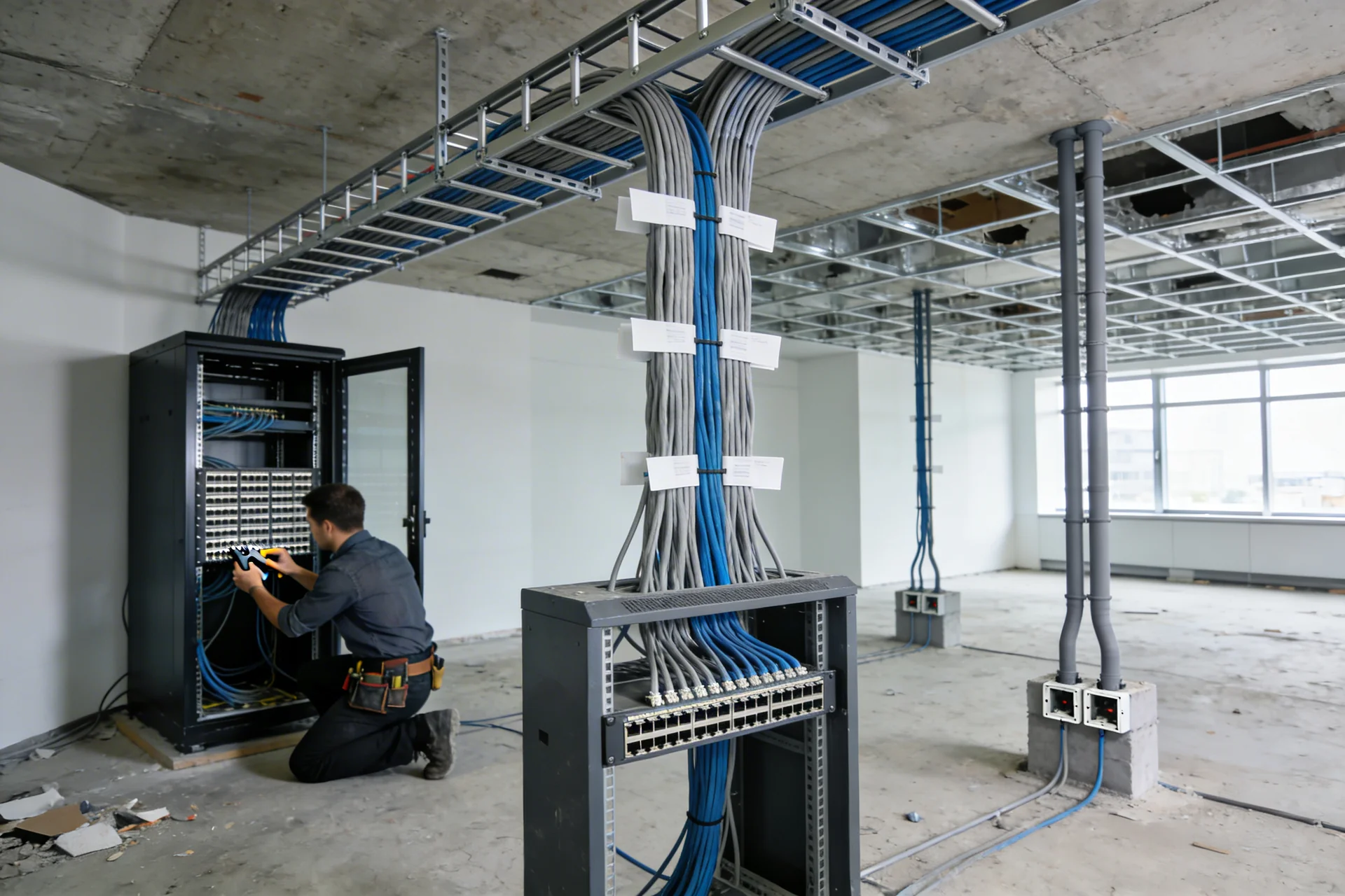
Structured Cabling Systems (SCS)


Working documentation: from 22 days
Price from 50000 roubles
We design structured cabling systems for any task - from workstations and server rooms to distributed sites - with a guarantee of high throughput, fault tolerance and readiness for scaling.
We design structured cabling systems for office centers, production facilities, warehouse complexes, data centers and distributed corporate networks. We study the SCS architecture, select equipment, create connection diagrams and switching nodes. The structured cabling systems that we create ensure stable data transmission, minimal delays and readiness of the infrastructure for further scaling.
Why does a poorly designed SCS cost more than redesigning it?
The answer is simple: an incorrectly designed SCS does not reveal itself immediately, but after a year or two of operation - when the office expands, a new floor opens, or a large tenant arrives, and it turns out that there are no free ports in the telecommunications cabinet, the cable trays are clogged, and the horizontal subsystem does not support 10 Gbit/s per workplace. No less problematic are uncoordinated routes, where SCS cables are laid parallel to power lines without observing separation standards - and the network is unstable for no apparent reason. As a result, the customer pays twice: for the initial installation and for partial or complete relocation.
AYU-Project designs structured cabling systems for office centers, manufacturing facilities, warehouse complexes, medical institutions and data centers. We develop design documentation and working documentation taking into account the current requirements of the customer and the estimated scaling horizon - so that in five and ten years the system is expanded with additional switching fields, and not rebuilt again.
What is SCS and why doesn’t any other system work without it?
A structured cabling system (SCS) is a universal physical infrastructure for transmitting data, voice and video over which LAN, telephony, security systems, video surveillance, building management systems and other engineering systems operate. The word “structured” means that the system is built according to a hierarchical architecture of standardized components - regardless of what active equipment is installed on it and what protocol it uses. This is the main difference between SCS and “spontaneous” cabling: the standardized physical environment works with any generation of active equipment and is reconfigured without re-wiring cables - only by switching patch cords on the cross-connect panel.
The regulatory basis for the design of SCS in Russia is GOST R 53246-2008 “Information technologies. Structured cable systems. Design of the main components of the system" and GOST R 53245-2008 “Installation of structured cabling systems”, harmonized with the international standard ISO/IEC 11801. Requirements for specific categories of cables and components are determined ISO/IEC 11801 (ed. 2017), and for telecommunications infrastructure data center - ISO/IEC 11801-5 (Part 5).
SCS architecture: three levels of hierarchy
Any SCS as required GOST R 53246-2008 is built in a three-level hierarchy, each level of which has a strictly defined function.
Trunk subsystem of the first level connects the main cross-connection (MC) with intermediate cross-connections (IC) - that is, it provides communication between campus buildings or between the main telecommunications room (GTP) and floor distribution points (ERP) for multi-story facilities. At this level, as a rule, a fiber optic cable (multi-mode OM3/OM4 or single-mode OS2) with high bandwidth and a large supply of fibers is used.
Trunk subsystem of the second level connects intermediate cross-connects (IC) with horizontal cross-connects (HC) in telecommunications cabinets of floors or zones. Here, too, optics or multi-pair, high-capacity copper cable are mainly used.
Horizontal subsystem - This is the connection from the horizontal cross-connect (HC) to the telecommunications outlet at the workplace. The length of the horizontal cable is no more than 90 m according to the standard. Twisted pair cable of categories 5e, 6, 6A, 7, 7A or 8 is used depending on the required speed, and in special cases - optical cable. Each socket is connected to the cross-connect panel with a separate individual cable using a “star” topology - without branches, splices or loops.
Which cable categories to choose for a modern facility?
The choice of cable category is determined by the required throughput, the type of facility and the prospects for network development. There is no point in saving on cable category when building a new facility - the cost of cable and sockets is only a small fraction of the cost of installation work, while reinstalling the horizontal subsystem in three years will cost much more.
| Category | Max. speed | Band (MHz) | Application |
|---|---|---|---|
| Cat 5e | 1 Gbit/s | 100 | Outdated; reconstruction only |
| Cat 6 | 1 Gbit/s (up to 55 m - 10 Gbit/s) | 250 | Basic office, small warehouse |
| Cat 6A | 10 Gbit/s up to 100 m | 500 | Office and business centers, Edge data centers |
| Cat 7 / 7A | 10-40 Gbit/s | 600 / 1000 | Production, data center, high-load sites |
| Cat 8.1 / 8.2 | 25-40 Gbit/s | 2000 | data center, server, rack-to-rack switching connections |
For most modern commercial facilities (business centers, shopping centers, medical institutions), the minimum recommended category is Cat 6A - it provides 10 Gbps up to 100 m and supports Power over Ethernet (PoE++) standards with power up to 90 W per port for IP cameras, Wi-Fi 6E access points, ACS controllers and industrial terminals.
Shielded or unshielded twisted pair?
Shielded cable (F/UTP, S/FTP, U/FTP) provides protection from external electromagnetic interference and reduces the level of its own radiation - this is important for facilities with powerful electrical equipment, industrial enterprises and medical institutions. Unshielded twisted pair (U/UTP) is easier to install and does not require a continuous grounding path along the entire route, but is less resistant to EMI.
The selection criterion is determined by the class of the electromagnetic environment at the facility and the requirements for the level of interference. At industrial facilities with frequency drives, transformer substations or extensive power infrastructure, the use of shielded cable is a prerequisite for stable network operation. In a typical office building without strong EMI sources, Category 6A UTP will fully provide the required performance.
For which facilities do we design structured cabling systems?
AYU-Project designs structured cabling systems for a wide range of B2B facilities:
- Office and business centers - cable infrastructure of workplaces, meeting rooms, server rooms; zoning by floor ERP; flexible configuration to suit the needs of tenants;
- Shopping and shopping and entertainment centers - infrastructure for cash register and POS networks, video surveillance systems, Wi-Fi, traffic management and BMS;
- Industrial enterprises - industrial SCS with shielded cables and high-protection components for industrial areas; clear separation of corporate and technology segments;
- Medical institutions - infrastructure with high requirements for noise immunity and reliability; cabling system for medical information systems (MIS), patient monitoring systems and EVAC;
- Data centers and server rooms - high-density cable systems of categories Cat 7/8 and FOCL, organized cable management systems, laying according to ISO/IEC 11801-5;
- Educational Institutions and Corporate Campuses - multi-level cable infrastructure of several buildings with a single main cross-connect and distributed ERP.
What is included in design documentation and working documentation by SCS?
Design and working documentation for SCS is developed in accordance with the requirements GOST R 53246-2008, GOST R 53245-2008, SP 134.13330.2022 And Government Decree of the Russian Federation No. 87 dated 16.02.2008 No. 87 (as amended on 21.10.2025) “On the composition of sections of project documentation and requirements for their content.”
Design documentation stage includes:
- an explanatory note justifying the architecture of SCS, the choice of cable category and component type;
- structural diagram of SCS with hierarchy of crosses;
- schematic diagram of the main subsystem;
- description of crossover spaces and telecommunications premises.
Working Documentation Stage (WD) contains:
- block diagram of SCS with a complete hierarchy of subsystems and designation of all cross-connections (MC, IC, HC);
- plans for the placement of cable routes (trays, ducts, pipes) with reference to construction axes;
- plans for placing telecommunications outlets at workplaces;
- layout diagrams of telecommunication cabinets and racks with the layout of patch panels and active equipment;
- diagrams for wiring cables on patch panels and cross-connects of the horizontal and backbone subsystems;
- scheme for debonding optical fibers on optical cross-connections (ODF);
- connection tables for horizontal and trunk subsystems (cable log);
- telecommunications grounding and potential equalization scheme;
- specification of equipment and materials;
- cable support system.
Telecommunication grounding as part of the SCS project
Telecommunication grounding is a mandatory element of SCS, which is often overlooked in “economical” design. All telecommunications cabinets, racks, metal cable support structures and cable shields must be connected to the Telecommunications Grounding Busbar (TGB) and then to the main grounding busbar (TMGB) of the site. This is a requirement ISO/IEC 11801 And ANSI/TIA-607, dictated not by formal rule-making, but by physical laws: the floating potential of metal structures during lightning events or switching overvoltages disables active equipment and creates a threat to personnel.
In our project, the telecommunications grounding diagram is developed as an independent drawing with the designation of routes, conductor sections and connection points to the main electrical installation - and is coordinated with the adjacent section of power supply.
Regulatory framework for SCS design
Documentation is developed in accordance with the following regulatory documents:
- GOST R 53246-2008 - design of main units SCS based on twisted pair and optical fiber; defines requirements for topology, line lengths, components and test parameters;
- GOST R 53245-2008 - installation of structured cabling systems: requirements for laying, bending radii, cable support systems, grounding;
- ISO/IEC 11801 (ed. 2017, parts 1-6) - international standard SCS; parts 2-5 regulate the requirements for office buildings, industrial facilities, residential buildings and data center;
- ANSI/TIA-568-C / TIA-568.2-D - American standard; used when designing for customers with international requirements;
- ANSI/TIA-607-C - telecommunication grounding and potential equalization;
- SP 134.13330.2022 - building telecommunication systems, in terms of general requirements for cable systems;
- GOST R 21.1101-2020 - general requirements for the design of WD;
- Government Decree of the Russian Federation No. 87 dated 16.02.2008 No. 87 (as amended on 21.10.2025) “On the composition of sections of project documentation and requirements for their content” - the mandatory inclusion of SCS in the composition of DD.
Cost and procedure for ordering design SCS
The cost of developing design documentation and working documentation is determined by the area of the facility, the number of workstations and sockets, cable category, the presence of data center or high-density server areas, the composition of cross-connect spaces and the number of floors. Approximate calculation - using the online calculator on the website.
To receive an accurate commercial proposal, leave a request: indicate the type and purpose of the object, total area, approximate number of jobs and available initial data - architectural plans, design assignment. The initial consultation is free, and we work across Russia remotely.
How to order the design of SCS: stages of work
- Submit an enquiry - the consultation is free
Form on the website or phone: +7 (383) 375-73-77 / +7 (923) 743-73-77. Indicate the type and purpose of the facility, total area and approximate number of workplaces. - Receive a Commercial Proposal Within 1 Business Day
CP with scope of work, cost and timing. When ordering an SCS together with a LAN, fiber-optic communication line or other sections of communication networks, you will receive a discount. - Approve the ToR and sign the contract
We clarify the stage of documentation (DD, WD or technical working draft), cable category, composition of cross-connect spaces, scaling requirements and deadlines. The contract fixes the composition and cost. - Analysis of architectural plans and site survey (if necessary)
We study floor plans, the location of utilities, wall and ceiling materials, and ceiling heights. If necessary, visit the site to clarify the conditions for laying routes. - SCS architecture development and cable category selection
We design a three-level hierarchy of crosses (MC-IC-HC). We justify the cable category of the horizontal subsystem taking into account the PoE load and scaling prospects. We determine the type of optical cable for the backbone subsystem (OM3/OM4 or OS2). We design a telecommunications grounding system (TGB/TMGB). - Design Documentation (DD) Development
Set DD according to Government Decree of the Russian Federation No. 87 (as amended on 21.10.2025) and GOST P 53246-2008: explanatory note with justification of the architecture, block diagram with hierarchy of cross-connects, schematic diagram of the backbone subsystem, description of cross-connect spaces. We eliminate the expert's comments free of charge. - Preparation of Working Documentation (WD) and Delivery to the Client
Complete installation kit: route plans with reference to building axes, socket location plans, cabinet layout diagrams with patch panel layout, cable disconnection and welding diagrams HVAC, cable log, telecommunications grounding diagram, specifications with articles, program of acceptance measurements. PDF and DWG formats.
Structured Cabling System Design Cost
| Scope of Work | Cost, rub. |
|---|---|
| Site inspection | Negotiable |
| Preparation of a commercial proposal (cost estimate) | Negotiable |
| Facility area, m2 | Cost, rub. |
|---|---|
| up to 100 | 35 000 |
| 100 - 399 | 60 000 |
| 400 - 799 | 90 000 |
| 800 - 1099 | 150 000 |
| 1100 - 2099 | 190 000 |
| 2100 - 3100 | 205 000 |
| Above 3100 | Negotiable |
Our Advantages


How We Work
Projects
Frequently Asked Questions
For a standard office property with an area of up to 5 000 m² - from 2 to 4 weeks for the PD stage, 3-5 weeks for the RD stage. For large multi-level facilities with TsOD zones or campus infrastructure - individually. The terms are fixed in the contract.
When designing, reserve ports are included in patch panels (as a rule, 20-25% of the filling), free space in cable trays for future routes (at least 30% of the free cross-sectional area), backup couplings in telecommunication cabinets and spare positions in cross-connections. The horizontal cable is laid from each workstation independently - adding a new workstation only requires connecting a new cable, and not reworking the existing infrastructure.
SCS - physical layer, LAN - active. They are designed interconnectedly: the SCS topology determines the location of the switches, and the LAN requirements (speed, VLAN, redundancy) influence the choice of cable category and the architecture of the cross-connect nodes. AYU-Project designs both sections in a complex, which eliminates contradictions between the physical and active layers of the network.
SCS certification testing - measuring the parameters of each cable line with a specialized tester (Fluke DSX, IDEAL) with confirmation of category compliance - is mandatory to obtain a system manufacturer's warranty (15-25 years) and is a requirement of many class A tenants. Our project includes a program and methodology for acceptance measurements, on the basis of which the installation organization conducts certification testing.
For a modern office with active use of IP telephony, IP video surveillance, Wi-Fi 6E and PoE++, a category of at least Cat 6A is recommended: it provides 10 Gbit/s up to 100 m, supports full PoE++ power (90 W) without overheating the cable in the bundle and is promising for the next generations of active equipment. Category 6 is acceptable in facilities with less intensive load and without high-power PoE devices.
The horizontal subsystem is a cable path from the telecommunications outlet at the workplace to the patch panel in the telecommunications closet on the floor (horizontal cross-connect, HC). The maximum length of horizontal cable is 90 m according to GOST P 53246-2008 and ISO/IEC 11801; the total length of the permanent line with patch cords is no more than 100 m. Each socket is connected to the patch panel with a separate individual cable according to the “star” topology - branches, splices and loops are not allowed.
Yes. If the design documentation has already been approved and passed expert review, we develop only working documentation based on it. To do this, you need an approved set of DD with architectural solutions, structural diagram and description of cross-over spaces. Cost and terms are calculated individually.
State expert review is mandatory for capital construction projects with government funding and for facilities that fall under the requirements of the RF Urban Planning Code. For commercial properties that do not require a building permit, a technical working design without undergoing an expert review is sufficient. AYU-Project accompanies documentation through state or independent expert review and eliminates comments free of charge.
To get started, all you need is: architectural floor plans (PDF or DWG); approximate number of workplaces and sockets; requirements for speed and cable category (if available); technical specifications or requirements for scaling and redundancy. If there are no plans, we will help you get them or conduct a measurement survey of the property.
Yes. Even for an office with 20-50 workstations, working documentation for the SCS is necessary: without it, the installer cannot accurately calculate cable lengths, determine the content of patch panels and cable trays, or provide a reserve for scaling. In addition, for capital construction projects, the section “Communication Networks” with a description of the SCS is mandatory according to Government Decree of the Russian Federation No. 87 (as amended on 21.10.2025) and SP 134.13330.2022.
Licences and Certificates


